2. Balancing Forces and Torques
- 2.10 Worked example: Calder's mobiles
2.10 Worked example: Calder's mobiles
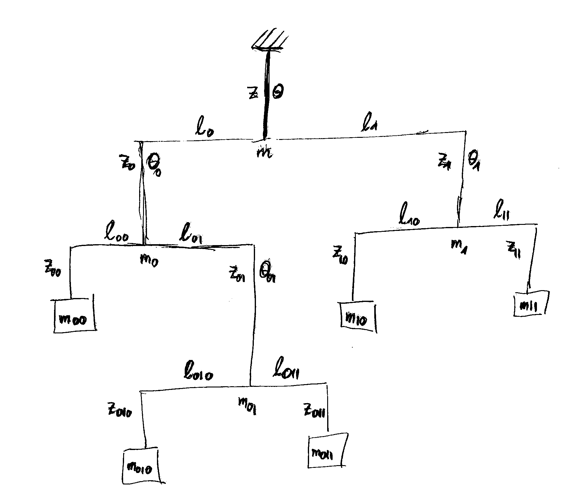
We describe here the setup of a traditional mobile where beams are supported by a string in the middle and balanced by attaching masses or further beams at their outer ends. The setup of a mobile can be laid out on a plane surface, as shown in Figure 2.25. The different parts of the mobile should not run into each other. Hence, they must not over overlap in the 2d layout.
 Figure 2.25:
Notations for the mathematical description of the motion of a mobile.
The mobile is suspended at a string of length $z$
that holds a beam with two sections of length $\ell_0$ to the left and $\ell_1$ to the right, respectively.
The string holds the total mass $m$ of the mobile.
When suspended, the beam can rotate by an angle $\theta$ out of the plane.
The left arm of the uppermost beam has length $\ell_0$,
and it holds another beam with an overall additional mass $m_0$
that can take an angle $\theta_0$ out of the plane in the suspended mobile.
Similarly, the right arm has length $\ell_1$,
and it holds another beam with an overall additional mass $m_1$
that can take an out-of-plane angle $\theta_1$.
The situation further down is described by hierarchical binary indices,
as indicated in the figure.
The mobile can represented as a binary tree. Each beam has two arms reaching left (0) and right (1). We assume that the mass of the beams may be neglected, and reach the masses at the far ends of the mobile, by going down from the suspension and marking the track by a sequence of $0$ and $1$. The leftmost mass, $00$, of the mobile in Figure 2.25 is reached by going left, $0$, twice. The next one in counterclockwise direction by going left $0$, right $1$, left $0$, and hence denoted as $010$, and so forth. Hence, the mobile is build of beams that are labeled by some index $I$. They support a total mass $m_I$, and can rotated out of the plane by an angle $\theta_I$. The beam has two arms of length $\ell_{I0}$ to the left and $\ell_{I1}$ to the right that support masses $m_{I0}$ and $m_{I1}$ attached to strings of length $z_{I0}$ and $z_{I1}$. This hierarchical setup of the descriptions allows us to reduce the requirement of stability by a condition that the forces and torques acting on the beams must be balanced. For the forces this implies \begin{align*} \mathbf F_I = \mathbf F_{I0} + \mathbf F_{I1} \quad\Rightarrow\quad m_I = m_{I0} + m_{I1} \end{align*} and for the torques we find \begin{align*} \ell_{I0} m_{I0} g = \ell_{I1} m_{I1} g \quad\Rightarrow\quad \ell_{I0} m_{I0} = \ell_{I1} m_{I1} \end{align*} When we take all masses to take the same value $m$ in Figure 2.25, we hence find \begin{align*} \ell_{010} = \ell_{011} \qquad\qquad \ell_{10} = \ell_{11} \qquad\qquad \ell_{00} = 2\, \ell_{01} \qquad\qquad 3 \, \ell_0 = 2\, \ell_1 \end{align*} Moreover, vector calculus provides an effective means to specify the positions of the masses. We select the support of the mobile as origin of the coordinate system. The support of the uppermost beam is at position $(0,0,-z)$. Then the far ends of the uppermost beam are at positions $\mathbf l_o = ( -\ell_0 \, \cos\theta , -\ell_0 \, \sin\theta , -z)$ and $\mathbf l_1 = ( \ell_1 \, \cos\theta , -\ell_1 \, \sin\theta , -z)$, respectively. Moreover, from the left end we reach the far ends of the next beam by the displacement vectors $\mathbf l_{00} = ( -\ell_{00} \, \cos\theta_0 , -\ell_{00} \, \sin\theta_0 , -z_0 )$ and $\mathbf l_{01} = ( \ell_{01} \, \cos\theta_0 , \ell_{01} \, \sin\theta_0 , -z_0 )$. Hence, the positions of the first two masses can be represented by the following sums of vectors \begin{align*} \mathbf q_{00} &= \mathbf l_{0} + \mathbf l_{00} - \begin{pmatrix} 0\\0\\ z_{00} \end{pmatrix} = \begin{pmatrix} -\ell_0 \, \cos\theta - \ell_{00} \, \cos\theta_0 \\ -\ell_0 \, \sin\theta - \ell_{00} \, \sin\theta_0 \\ -z -z_0 - z_{00} \end{pmatrix} \\ \mathbf q_{010} &= \mathbf l_{0} + \mathbf l_{01}+ \mathbf l_{010} - \begin{pmatrix} 0\\0\\ z_{010} \end{pmatrix} = \begin{pmatrix} -\ell_0 \, \cos\theta + \ell_{01} \, \cos\theta_0 - \ell_{010} \, \cos\theta_{01} \\ -\ell_0 \, \sin\theta + \ell_{01} \, \sin\theta_0 - \ell_{010} \, \sin\theta_{01} \\ -z -z_0 - z_{01}- z_{010} \end{pmatrix} \end{align*} We urge the reader to also work out the expressions for the positions of the other masses.
